
Shielded wire is used for sensors which monitor critical engine systems. Some examples include knock sensors, crankshaft sensors, and camshaft sensors.
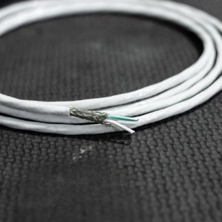
As crank and cam sensors are critical to the operation of the engine the signal they send to the ECU must be as clear as possible. Keeping this signal clear is where shielded wire comes in. Shielded wire has a core run of wire or wires which are wrapped in a copper braid and then another layer of insulation over the top. The copper braid cover is the important part as this braid provides protection from electronic interference.
Electronic interference is usually generated by the rapid switching of power, unfortunately in the case of cars, injectors and ignition coils are always rapidly switching on and off.
To protect your sensitive wires against electrical interference (also called noise), you can either shield the sensitive wires to keep the interference “out”, or shield the interference generating wires themselves and keep the interference “in”. Both techniques work and are used by oem manufacturers, but we generally shield the sensor wires due to the ease of sourcing multi-core shielded wire in a small gauge compared to in a larger gauge.
In order for the shield to work correctly it needs to be wired so it can “drain” to ground. Only one end of the shield should be connected to ground to ensure we don’t violate star-earthing best practice.
To terminate the drain a splice can be used to join a wire to the shield or a solder sleeve can be used.
How to terminate a shield drain
The first step, no matter which type of termination you are using is to strip the insulation off the braid. To do this, use a sharp knife to score the insulation (don’t cut too deep or you will damage the shield and possibly the core wires). Once scored flex the wire a little to ensure the insulation has totally split along the cut mark.
To help with removing the insulation slug a small piece of sandpaper can be used to help with gripping the slug.

At this point the next step depends on which type of termination you are performing.
Using a Splice
After removing the insulation you should push the shield back so it bunches near the base of the stripped section.

Then, carefully using a pick tease each wire out from under the insulation.


Now we are ready to crimp our drain wire to the shield.
Lay the shield and the drain wire in the splice so that both are entering the splice from the same direction.

Perform the crimp.

Lay the crimp up next to the covered section of shielded wire and use glue-lined heat shrink like SCL or ATUM to insulate and provide strain relief to the joint.

Your drain wire is now ready to connect to the ECU or ground point (ensuring not to ground both ends).
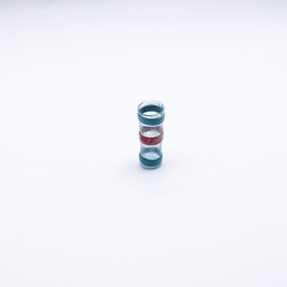
Using a Solder Sleeve
After removing the insulation slug, carefully trim the braid back flush with the remaining insulation.

Next remove another slug of insulation aiming to have a length of braid exposed that will fit between the sealing rings of the solder sleeve with roughly 2mm of clearance on either side.

Slide the solder sleeve over the shield and insert the drain wire ensuring the centre line on the solder sleeve is over both the shield and the stripped section of drain wire.

Recover the solder sleeve.
The recovery is complete when the red colour in the centre of the solder sleeve is gone (some manufacturers like TE Connectivity use yellow in their solder sleeves, but the colour will still disappear when recovered).

Your drain wire is now ready to connect to the ECU or ground point (ensuring not to ground both ends).
What to do at the non-drain end
When draining your shield at the ECU end of the wire then the connector end of the wire just needs to have the insulation and shield trimmed back enough to allow the connector to be attached at the end.


While you can ground the shield at the sensor end of the wire there are other factors to consider and we generally avoid doing this.
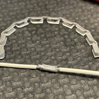
Bulkheads and shielding
If your harness isn’t travelling in a single length from the sensors to the ECU you may have more than one run of shielded wire.
If you have the room on your bulkhead connector you can run the shield through the bulkhead itself by terminating a wire to the shield and then using a spare pin on the bulkhead connector to connect it to the shield on the other side.

In this example, the shield wire goes into cavity 9 on this side of the connector.

The next run of shielded wire is joined to the first through cavity 9 on the other side of the connector.

With both shields joined together, the side which runs to the ECU can have the shield terminated to a drain wire and grounded to the ECU.
If you don’t have a spare cavity in your bulkhead connector you can still shield your wires, but each section needs to be treated individually. The engine bay side should have its shield drained to ground, and the cabin side should have its shield drained to ground.

Where to ground the drain to?
Each ECU manufacturer will have their own suggestions for where to drain the shield to. Best practice is to use the ECU wiring diagram for the ECU you are wiring up.
A few common ECU manufacturers are listed below with their preferred shield drain location.
Haltech and Link ECU say to connect the shield to the Signal Ground.
ECU Master say to connect the shield to the Power Ground.
Emtron have a Shield pin on the ECU Connector
As always PT Motorsport are here to help, if you have any further questions after reading this article, please let us know!
-
 Raychem Solder Sleeve Splice$4.60
 -
 Shielded Wire$4.95 – $12.90
 -
 Open Barrel Splice$0.34 – $0.36